How to verify coverage, tracking, false-alarm performance, EO/IR cueing and evidence before accepting a drone detection radar system
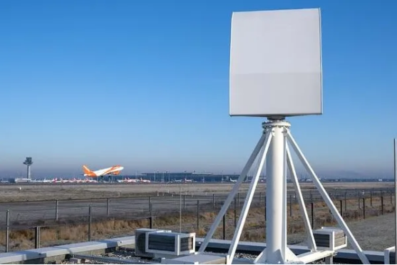
Figure 1. An acceptance plan should reflect the actual site, installed sensor position and operating environment.
| Acceptance principle: Do not accept a drone detection radar against a supplier-controlled demonstration alone. A valid acceptance decision is target-specific, site-aware, repeatable and supported by retained evidence that the buyer can independently review. |
Recommended SEO Publishing Package
| Element | Recommended value |
| SEO title | Drone Detection Radar Field Test & SAT Guide: How to Verify Performance |
| H1 | Drone Detection Radar Field Testing and Site Acceptance Guide |
| URL slug | drone-detection-radar-field-test-site-acceptance-guide |
| Meta description | Learn how to field-test and accept a drone detection radar system with target routes, ground truth, false-alarm measurement, EO/IR cueing, FAT, SAT and retained evidence. |
| Primary keyword | drone detection radar field test |
| Secondary topics | drone radar site acceptance test, counter-UAS SAT, radar ground truth, drone detection acceptance criteria, EO IR cueing test |
| Featured image alt | Drone detection surveillance radar installed near an airport perimeter |
What a Valid Drone Detection Radar Acceptance Test Proves
A drone detection radar system should be accepted against the buyer’s approved target set, site geometry and operator workflow. The purpose of field testing is not merely to show that a radar can see an object. It is to verify that the installed system creates usable warning time, stable tracks, correctly delivered cues and reviewable evidence under agreed operating conditions.
· The installed coverage corresponds to the approved site design and stated residual blind zones.
· The system detects, initiates and maintains tracks for representative targets and routes.
· False alarms, environmental limitations and degraded behaviors are measured rather than assumed.
· EO/IR and command-platform integrations receive the correct data in time to support the workflow.
· The buyer receives sufficient raw and processed evidence to reproduce the acceptance decision.
Use the Drone Detection & Low-Altitude Surveillance Radar Procurement Guide to establish the threat model and architecture before preparing this test plan.
See also: Smart Home Technology Overview
1. Freeze the Test Baseline Before the First Flight
No test result is meaningful unless the configuration it represents is controlled. Before the first run, record installed sensor coordinates and heights, active sectors, radar mode, software and algorithm versions, clutter maps, camera calibration, network path, time source and approved coverage drawing. If a material setting changes, the change must be logged and the affected scenario repeated.
| Baseline item | Evidence to freeze |
| Sensor installation | Coordinates, elevation, orientation, mounting height, cabling and antenna/radar configuration |
| Software and settings | Software version, licenses, radar mode, zones, classification threshold and configuration export |
| Coverage model | Model inputs, obstructions, expected blind zones, overlap and residual-risk statement |
| EO/IR integration | Camera boresight/calibration, PTU limits, preset rules and cueing configuration |
| Network and time | Network path, latency assumptions, time source, synchronization status and timezone |
| Test environment | Weather, temporary obstructions, construction activity and unavailable interfaces |
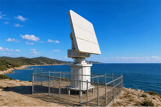
Figure 2. The test record should identify the exact installed radar position, mounting height and local obstruction conditions.
2. Separate Proof of Concept, FAT, SAT and Operational Acceptance
A successful proof of concept does not replace a site acceptance test. Each stage answers a different question, and each should identify what remains unproven. The contract should name the stage, objective, location, target conditions, evidence package and consequence of failure.
| Stage | Primary decision | Typical location |
| Proof of concept | Can the proposed architecture address the target and interface concept? | Supplier or representative site |
| Pre-award field trial | Can the offered configuration perform under buyer-relevant targets and conditions? | Buyer or technically representative site |
| Factory acceptance test | Was the contracted configuration built, configured and documented correctly? | Supplier facility |
| Site acceptance test | Does the installed project meet contracted performance and integration requirements? | Deployment site |
| Operational acceptance | Is the contracted capability sustainable during routine operation? | Deployment site over an agreed period |
3. Design Representative Targets, Routes and Ground Truth
The target schedule should describe the drones and flight behaviors that matter to the site. It should identify the representative multirotor, fixed-wing or VTOL class; physical dimensions or agreed radar cross-section basis; payload condition; speed; altitude; aspect; route; and whether the target is approaching, crossing, receding or hovering. Do not report one maximum range without these conditions.
· Radial approach and departure routes to measure range and track establishment.
· Crossing and tangential routes to expose aspect sensitivity and track continuity.
· Hovering or slow movement where low-velocity behavior is operationally relevant.
· Low-altitude paths that exercise terrain, buildings, vegetation and near-range effects.
· Multiple-target scenarios if capacity, identity stability or deconfliction is required.
· Day, night or adverse-condition runs only where they reflect the contracted operating envelope.
Ground truth is the reference for every measurement
Ground truth may use surveyed waypoints, GNSS telemetry, synchronized video, independent tracking equipment or a combination of methods. Define the authoritative clock, permitted offset and uncertainty before the test. Retain the raw timestamps and synchronization evidence; without them, range, latency, cueing error and track accuracy cannot be evaluated defensibly.
4. Measure Detection, Tracking and Classification Separately
A transient plot is not the same as a confirmed track, and a confirmed track is not the same as a verified target. The test plan should define the event that starts the warning-time clock and the thresholds that distinguish initial detection, track initiation, stable tracking, classification support and alarm generation.
| Performance stage | What to record |
| Initial detection | First valid detection time and range under the agreed confirmation rule |
| Track initiation | Time and position at which a tentative or confirmed track is created |
| Stable tracking | Continuity, permitted losses, reacquisition, update rate and quality threshold |
| Classification | Class label, confidence, latency, unknown handling and known error cases |
| Alarm generation | Zone logic, alarm delay, suppression, escalation and operator acknowledgement |
| Data export | Timestamp, track ID, coordinates, quality, update behavior and downstream receipt |
| Contract-ready example: For the agreed reference multirotor and route set, the system shall create a valid track within [X] seconds after the target enters the verified coverage volume and shall not lose the track for longer than [Y] seconds without documented reacquisition behavior. Verification requires synchronized ground truth and retained radar logs. |
5. Measure False Alarms Under Normal Site Activity
False-alarm performance should be observed while the site is operating normally. Birds, vehicles, vegetation, machinery, waves, precipitation and authorized aircraft may all matter, depending on the location. A classification percentage obtained from a laboratory dataset cannot substitute for a site-specific nuisance-alarm observation.
· Observation duration, date, time and active surveillance zones.
· Radar mode, sensitivity, software version, classification settings and alarm rules.
· Environmental conditions and relevant site activity during the observation period.
· Alarm count, duplicate handling, operator suppression and manually resolved events.
· Known exclusions, maintenance windows and any degraded state.
6. Test Radar-to-Camera Cueing and the Operational Chain
A claim that a radar exports coordinates is not an acceptance result. The integration test should measure the entire chain from radar track creation to target presentation in the EO/IR camera and command platform. Verify coordinate frames, terrain and altitude assumptions, timestamps, network latency, PTU motion and settling, boresight calibration, field-of-view selection, track identity and event mapping.
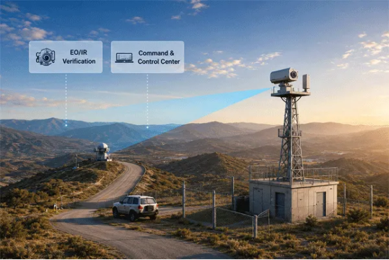
Figure 3. Radar-to-camera acceptance must verify the complete cueing and confirmation chain, not only the availability of an interface.
For the broader sensor roles and cueing architecture, review Midradar radar-vision fusion systems.
| Integration checkpoint | Acceptance evidence |
| Track message | Captured message containing identity, time, coordinates, velocity and quality fields |
| Coordinate conversion | Known-point or representative-route error record, including datum and altitude assumptions |
| Camera cueing | Target-in-frame result at defined range, field of view and time |
| Video and metadata | Synchronized recording with event, track and operator action association |
| Failure behavior | Documented response to sensor, network, service or time-synchronization loss |
| Operational client | Track, alarm and acknowledgement visible in the proposed command or VMS/PSIM platform |
7. Define Repeatability, Retest and Exception Rules
The plan should define the required number of runs, whether results are evaluated per run or across a series, and what makes a run invalid. A failed scenario must not be replaced by an easier route, a different target or a new system setting without a controlled deviation and retest record.
1. Record the original scenario, target, route, configuration and reason for any interruption.
2. Classify the event as valid failure, invalid run, supplier fault, buyer dependency, weather interruption or approved deviation.
3. Document every setting change, including clutter filter, classification threshold, zone or camera preset adjustment.
4. Repeat the affected scenario using the final intended configuration.
5. Lock and export the accepted configuration as the baseline for later operation and dispute resolution.
8. Retain an Evidence Package the Buyer Can Review
A signed pass/fail statement alone is insufficient for a complex surveillance system. The buyer should receive a controlled evidence package that makes the acceptance calculation repeatable and exposes the conditions under which it was performed.
| Evidence package | Minimum contents |
| Approved plan | Test objectives, routes, targets, roles, thresholds, retest rules and safety controls |
| Configuration baseline | Installed layout, settings, software versions, licenses, calibration and time source |
| Raw and processed data | Radar tracks, event logs, original video, interface captures and ground-truth records |
| Environmental record | Weather, clutter, obstructions, active zones and exceptions |
| Results and closure | Pass/fail calculation, deviations, retests, corrective actions, limitations and signatures |
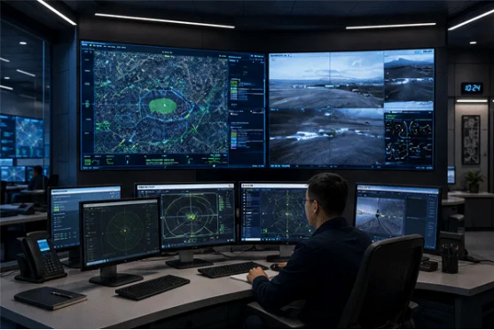
Figure 4. Retained tracks, alarms, video and operator actions should show how the system performed as an operational whole.
9. Link Contract Milestones to Measurable Outputs
Payment and acceptance milestones should be linked to controlled outputs: approved design documents, successful FAT, delivered equipment, completed installation, passed SAT and closure of agreed punch-list items. Avoid milestones based solely on shipment or power-on when the contract objective is an integrated detection and verification capability.
· Approval of coverage drawings, interface control documents and the test plan.
· FAT completion against the contracted configuration and documented interfaces.
· Installation completion with as-built drawings, calibration and health checks.
· SAT completion with target runs, ground truth, integration evidence and accepted limitations.
· Operational acceptance period where seasonal clutter, software stability or operator workflow risk justifies it.
After technical acceptance is established, use the surveillance radar quotation comparison guide to normalize the commercial proposals on a like-for-like basis.
10. Build the Test Plan Around the Actual Workflow
The best field test is not the one with the most flights. It is the one that proves the system’s ability to support the response workflow: detect the relevant target, create a usable track, cue the verification sensor or operator, log the event and preserve evidence. The test plan should make every handoff visible.
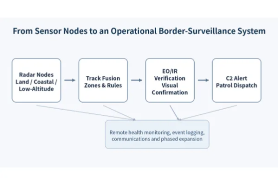
Figure 5. A field test should prove the full warning and verification workflow, including the handoff from radar detection to response.
Frequently Asked Questions
Should field testing be performed only at the supplier site?
No. Supplier-site testing can confirm basic function, but it cannot prove buyer-site coverage, clutter behavior, network performance or operational integration. Those elements must be verified at the deployment site or a technically representative location.
How long should false alarms be observed?
The observation period should represent the site’s normal activity and risk. Define duration, operating conditions, active zones, weather limits and alarm treatment in the test plan rather than relying on a short, undocumented demonstration.
What data should the buyer receive?
At minimum: radar tracks, timestamps, ground truth, relevant video, event logs, interface captures, configuration settings, software versions, environmental records and a signed report explaining the pass/fail calculation and remaining limitations.
When should acceptance criteria be agreed?
Before contract award. Late definition creates avoidable disputes about targets, routes, settings, environmental conditions and what constitutes a pass or a valid retest.
Does Remote ID replace radar field testing?
No. Remote ID is a cooperative source and may not be available from every target. Radar and other non-cooperative sensors should be tested against the agreed threat set. For United States context, consult FAA Remote ID guidance and obtain project-specific legal advice.
Conclusion
A defensible drone detection radar field test is repeatable, target-specific, site-aware and evidence-backed. It separates first detection from stable tracking, measures false alarms and integration, uses synchronized ground truth and retains the underlying records. This lets the buyer accept an operational capability, not a brochure claim or an undocumented demonstration.
Need a site-specific field-test and acceptance plan? Contact the Midradar technical team to define routes, ground truth, data capture and acceptance criteria for the proposed site.